Customized DR system solution
As a high and new tech enterprise, HATATEST has always been in the forefront of innovation. In order to better serve customers,we provides "private custom" module. According to the needs of customers and the problems to be solved, we will customize the automated testing equipment for customers to help them save manpower and material resources and improve the detection efficiency.
Here is a successful case sharing. This is a fully automated digital X-ray inspection system for large pressure vessels. You will see detailed customized DR system solutions including design ideas, mechanical composition, finished product pictures, etc.
The design technical principles are as follows
- 1. The four-section conveyor line can smoothly and accurately synchronize the docking conveyor tank;
- 2. the tank body translation rotation is stable and reliable;
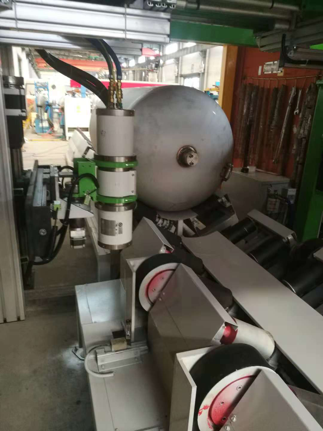
- 3. The ray machine has the functions of lifting and traversing feed and rotating ray window;
- 4. The flat panel detector has the functions of lifting, traversing and feeding;
- 5. The C-arm rotates obliquely, traverses and stretches, and the focusing drive structure has high precision, stability, rigidity, and large anti-overturning force, ensuring stable displacement and clear image imaging without jitter;
- 6. the inside and outside of the lead room, C-arm important position to install the camera, easy to manually lead the room, equipment, fast and accurate, safe and reliable operation;
- 7. Under the premise of ensuring quality and use requirements, the design cycle and processing cycle are shortened as much as possible, and the overall system has the requirements of rapid maintenance and quick change of parts.
The design ideas are as follows
- 1. The whole system adopts standardized design and modular design. 80% of the raw materials of parts and components are preferred standard products on the market, and the equipment is quickly built;
- 2. The inlet and outlet connection lines and cache lines are driven by a V-type power roller line. The bottom frame is constructed of profile profiles and the drums are made of standard products;
- 3. The detection line segment is modified by the mature plate chain line, and the fixed support wheel is added to the plate. The rotation adopts the symmetric arrangement to approach the friction wheel drive technology;
- 4. The displacement mechanism of the ray machine and the flat-panel detector adopts the truss type displacement mechanism, the main body is constructed with aluminum profiles, the linear drive adopts the standard servo electric cylinder technology, and the rotation of the ray machine is driven by the hollow rotary table motor;
- 5. The mounting bracket of the ray machine and the flat plate requires good rigidity and stable structure, ensuring stable and reliable imaging when focusing;
- 6. All motion modules of the total system adopt safety protection technologies such as travel switch and mechanical anti-collision to ensure safe and reliable operation of all links in the system;
- 7. One lead-in and one-out surveillance cameras are installed in the lead room, and one camera is installed in the lead-indoor super-export direction. In order to facilitate the operator to operate the displacement device simply and safely, to avoid the safety of the flat panel detector, and to ensure the rapid positioning of the detection area, a camera is arranged on the C-frame parallel plate for judging the distance between the workpiece and the flat panel detector. At the same time, the camera is installed on the ray machine mounting plate, which is convenient for quickly and intuitively positioning the detection area.
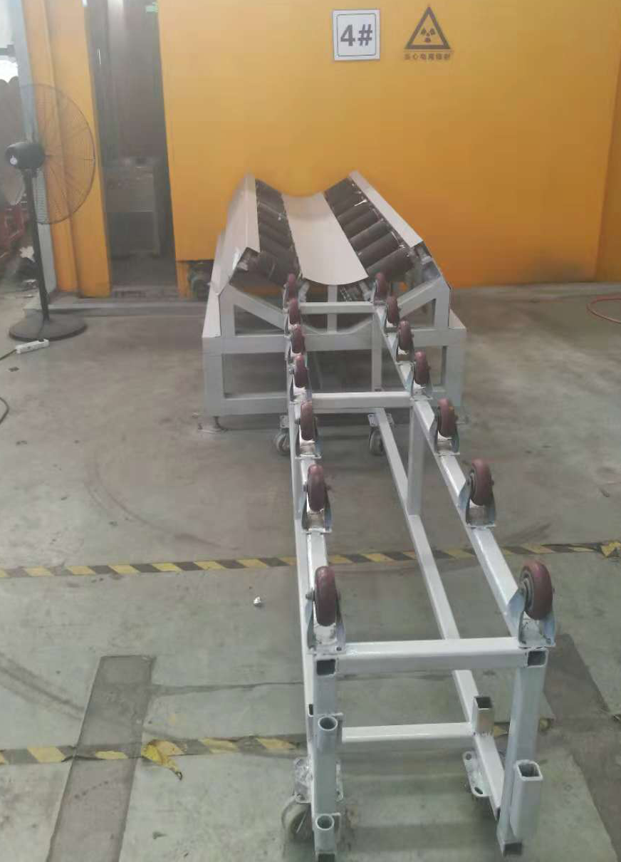
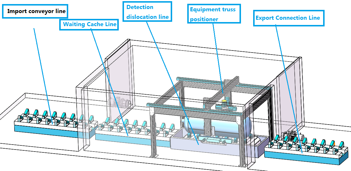
Figure 1 Schematic diagram of the overall layout
Mechanical system composition
The mechanical system consists of an inlet conveyor line, a waiting buffer line, a detection displacement line, an outlet connection line, and a detection device truss positioner.
The inlet conveyor line, the outlet buffer line, and the waiting cache line are exactly the same. The V-shaped power drum line is used to realize the tank body transportation, the machine body is simple, easy to maintain, and the operation is stable.
The detecting displacement line adopts the caster supporting plate chain line, and the two sides are symmetrically installed with the propulsion friction driving wheel axle mechanism to realize the tank conveying and turning, the structure is simple, mature, stable, easy to maintain and stable in operation.
The detecting device positioner adopts large-section aluminum profile to build the frame, adopts linear electric cylinder and rotary motor to drive the displacement, realizes the displacement function of the ray machine and the flat plate, and the system is simple, mature, stable and easy to maintain.
Working principle
After the detection is completed, the system automatically turns off the ray machine, and the inlet and outlet doors are automatically opened. After the door body is opened, the electrical switch in place is fed back to the system, and the four-segment line body is synchronously started. The detected workpiece is output to the connection line, and the buffer is waiting. The inspection product is transported to the inspection line, and the imported product is transported to the cache line to simultaneously complete the workpiece conveyance. Each line body is provided with a detection photoelectric switch, and after the feedback product is in place, the line body stops moving. Subsequently, the import and export door is automatically closed, and the operator quickly docks the device and the workpiece with the aid of the surveillance camera to complete the positioning of the weld before the inspection. The person can turn on the ray machine and start the automatic detection program with one button.
Note: It is also possible to form a database according to the corresponding automatic detection program of most of the customer's workpieces. The system can add the product model QR code to realize product identification, automatically retrieve the corresponding detection program and realize detection. Manual input of product information is also supported.
Mechanical system advantages
- 1. The overall system design is clever, simple and practical, and innovative;
- 2. The system is simple in operation, convenient in maintenance, simple and reliable in operation;
- 3. The system adopts standard raw materials and standard parts commonly used in the market, and the assembly is simple;
- 4. All displacement movements are equipped with limit switches and mechanical limit to ensure the double safety of the system movement;
- 5. the system configuration global surveillance camera PTZ, tablet security distance monitoring camera, detection area positioning camera, greatly improving the work safety and efficiency.
Technical parameters
|
Item
|
Project
|
Parameter
|
|
1
|
Detecting diameter range
|
650~ 1100mm
|
|
2
|
Detection length range
|
700~2200mm
|
|
3
|
Detect workpiece load capacity
|
≤1T
|
|
4
|
Detecting beats
|
≤8min
|
Electrical Control System
- 1. The electric control cabinet complies with IEC 61439-1:2011, and the cabinet has door opening lighting facilities and adopts air cooling and cooling;
- 2. The layout of each part of the system is reasonable and separately controlled. Install limit safety switches for each direction of axial movement. The system uses key power control, and the console emergency button facilitates emergency troubleshooting. It has safety interlock protection and alarm function when the conditions do not meet the exposure requirements or misoperation;
- 3.Air switch, circuit breaker, AC contactor, Schneider brand; sensor, intermediate relay using Omron brand products;
- 4.All motion axes use servo motors to drive Siemens brand products.
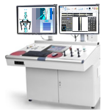
Console
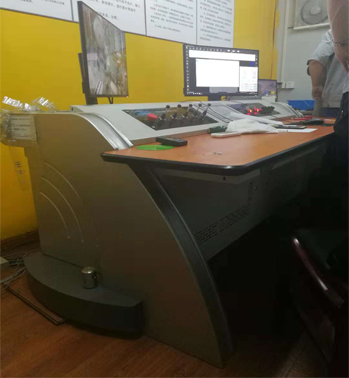
Figure 3 Schematic diagram of the monitoring screen
The console selects the most popular and stylish top-notch in the world. It is equipped with two large-screen displays, one for monitoring and one for software control and imaging.
Configure a high-end configuration host
- Host: 3000 type
- 128GB SSD+1TB hard drive, 8G memory
- CPU: seventh generation I5-7400 processor
- 2GB high resolution discrete graphics
- DVD drive
- 4K HD IPS screen display: 32 inches
- Professional flat panel imaging software system
Monitor the displacement operation
The system sets up 6 surveillance cameras. The console is equipped with a monitor display that supports multi-screen display and switch display. As shown below
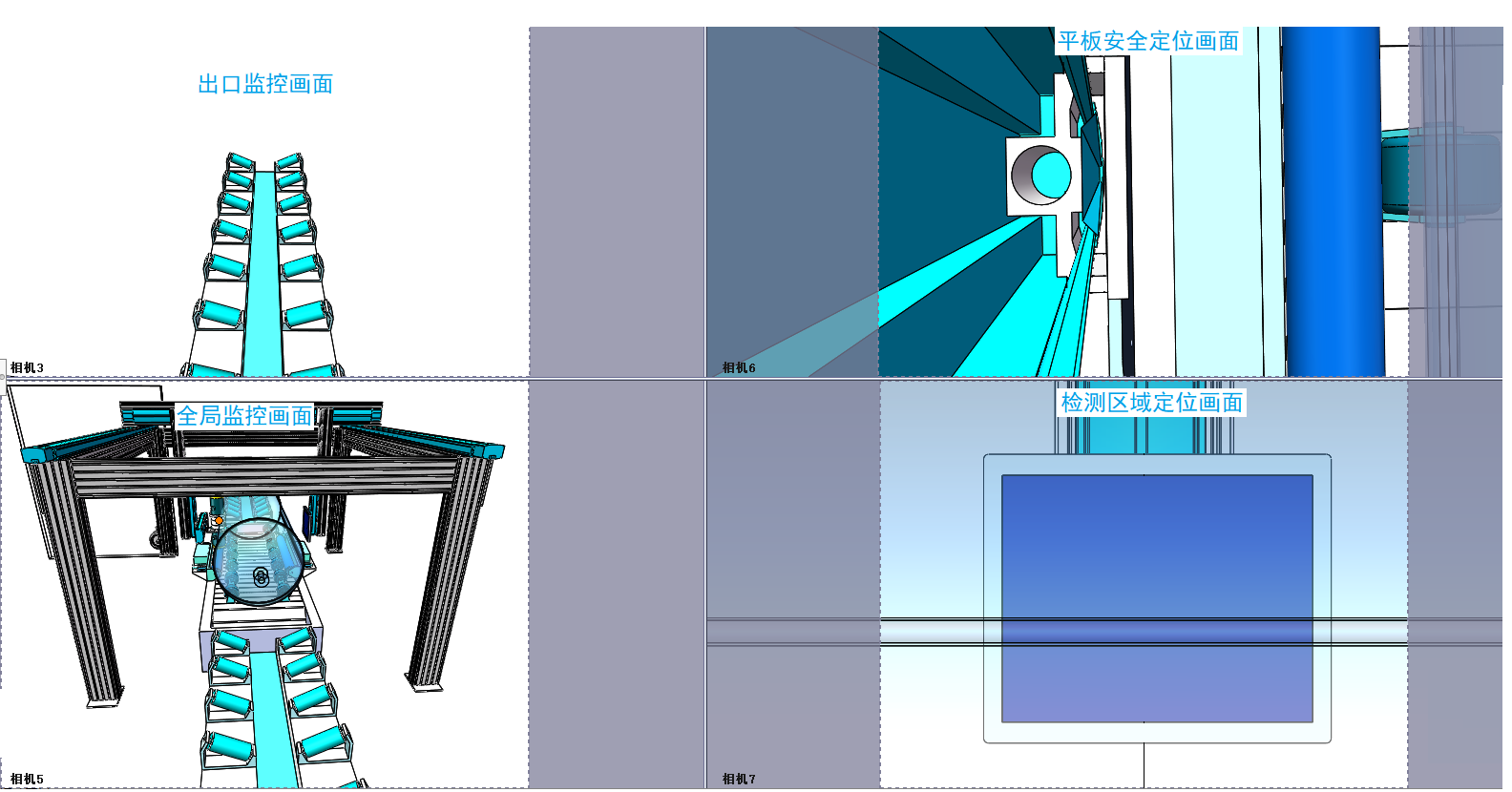
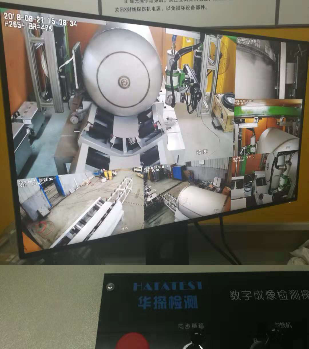
Figure 4 Schematic diagram of the monitoring screen
Control and imaging display
The system selects a large-screen display, and the device control system, imaging display, and imaging control system are integrated into one software screen through soft. Make the manipulation operation more user-friendly and convenient.
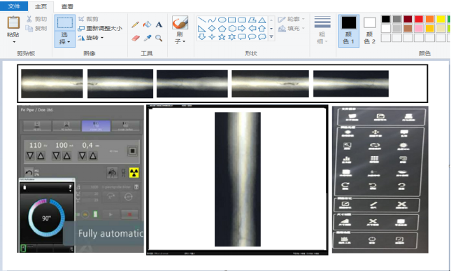
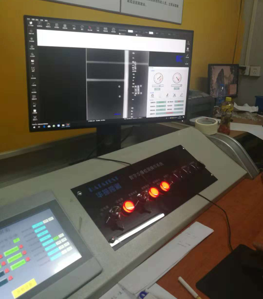
Figure 5 shows the layout of the display